

EXPERT ADVICE
Professionals in refrigeration technology

SINCE 1986
Since 1986 in refrigeration technology

FACTORY GUARANTEE
You have Always genuine manufacturer's warranty

CUSTOMER SERVICE
info@mfmref.com
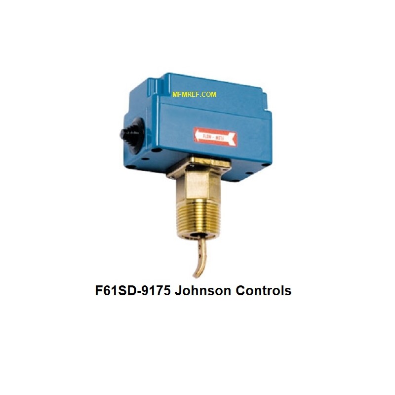
Johnson Controls Mechanical liquid flow switch
The F61 liquid flow switches can be used in liquid lines carrying water,
sea water, swimming pool water, ethylene glycol or other liquids not
harmful to the specified materials.
The switches have SPDT contacts and can be wired to energise one
device and de-energise another when liquid flow either exceeds
or drops below the set flow rate. Pipe insert models and the T-body
types for low-flow applications are available.
The IP43 versions can be used for liquid temperatures above dewpoint
Typical applications are to shut down the compressor on liquid chiller
systems, to prove flow on electric immersion heaters and to give
a signal or alarm when the pump on condenser cooling system shuts down.
Pipe-insert types
To allow the switch to detect changes in the liquid flow, the paddle must not touch the pipe or any other obstacle in the pipe.
The Pipe-insert types are mounted on top of the liquid line.
An angle of 120° is allowed as indicated in Fig. 1.
To keep the flow switch close to the pipe and to provide an adequate paddle length in the flow
stream the use of a reducing tee for larger pipe sizes is advised.
The arrow on the cover must point in the flow direction.
To avoid turbulence it is advised to mount the controller at a distance
of minimal 10xD (on each side) away from elbows, valves and other appendages.
The Pipe-insert types can be mounted in a vertical pipe as long as the flow is up-stream.
This mounting position affects the adjustment of the controller.
The 6” paddle can be trimmed as indicated on page 6.
For added stiffness it is advised to mount the smaller paddles behind the largest one
The switches are factory set at minimal flow setting.
On the application the setting can be adjusted by the range screw under the cover as
indicated in fig. 3. For higher flow rates turn the adjusting screw clockwise.